7.0
OPERATIONS
The
TRACE-P mission deployment depends upon the coordinated efforts
of many persons and organizations. The
following sections provide details for each activity associated
with the deployment sites, the Team members and airplanes. Table
7.0-1 provides a one-page summary of these activity and
indicates who is involved in their implementation.
7.1
Functional Organization
TRACE-P is a research
project within the NASA Global Tropospheric Experiment (GTE) series,
managed and funded through the Tropospheric Chemistry Program in
the Earth Science Enterprise
Office (ESEO). The
Program Manager for the Tropospheric Chemistry Program serves as
the TRACE-P Program Manager. TRACE-P
Project activities are managed by the GTE Project Office at NASA's
Langley Research Center (LaRC).
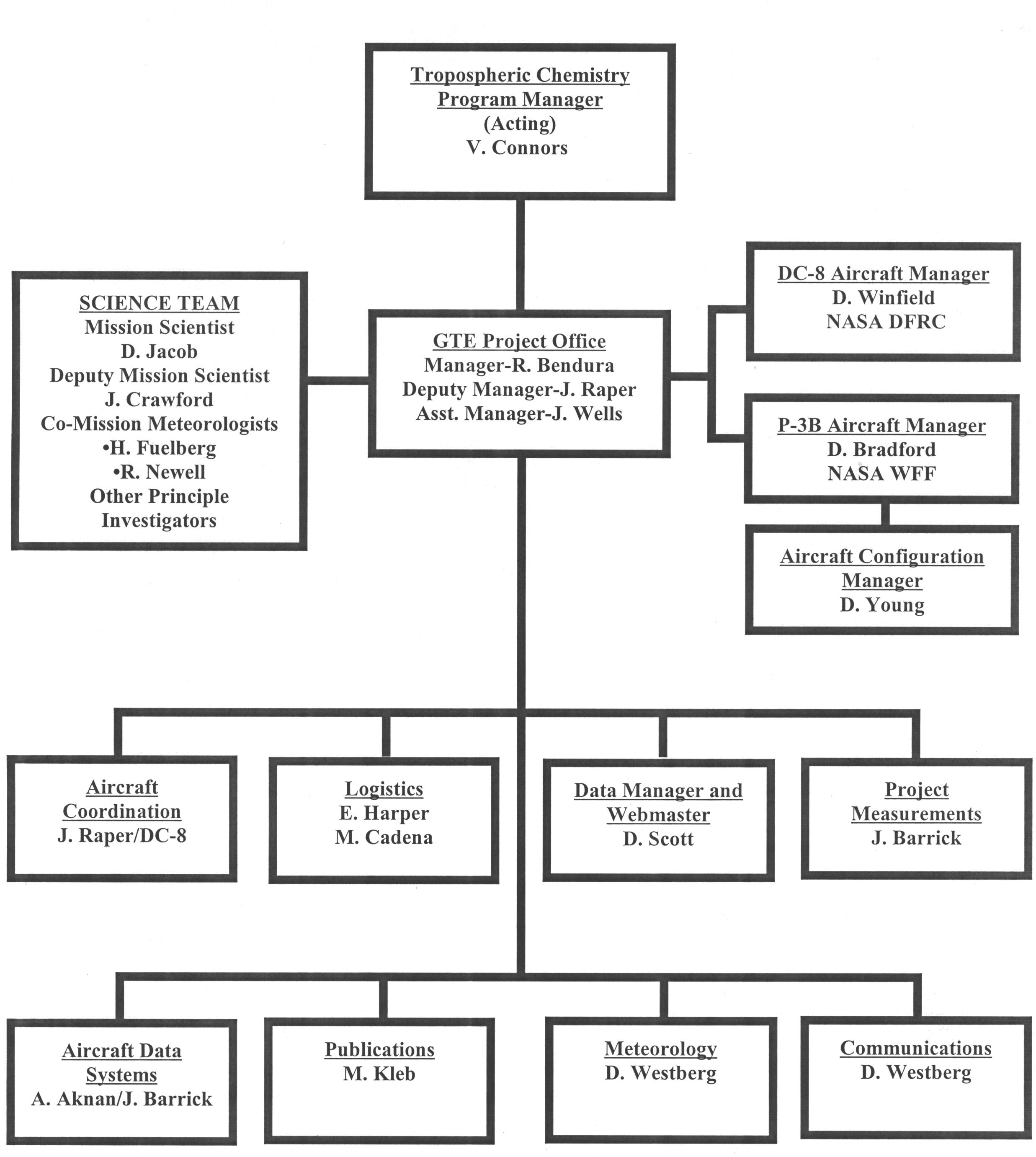
The functional organization for implementing GTE/TRACE-P is shown
in Figure
7.1-1. Names,
organization and telephone numbers of all project personnel are
provided in Appendix H.
A brief description of the TRACE-P team responsibilities for major
functional elements follows:
Tropospheric
Chemistry Program Manager: Provides oversight to ensure
that the research activities of TRACE-P are in concert with the
objectives of the ESEO. The
Program Manager will be the point of contact for coordinating
the research activities of TRACE-P with other collaborating U.S.
and foreign agencies, if applicable. The
Program Manager will be an ex-officio member of the TRACE-P Science
Team.
GTE Project Office: The GTE
Project Manager, with the assistance of the Deputy Project Manager,
will be responsible for the overall management and coordination
of resources provided to meet the scientific objectives of the
TRACE-P mission. These
responsibilities will include (a) interaction with the Tropospheric
Chemistry Program management and the management of other collaborating
agencies and science teams; (b) overall direction and documentation
of project planning, schedules, and field operations; (c) providing
for the timely transmittal of all data collected by the project
into the LaRC DAAC; and (d) acquisition and reporting of base measurements
in support of the mission goals. Also,
in concert with the NASA Office of External Affairs and the U.S.
Department of State, determine and assure compliance with host
country requirements for foreign country operations. The Project
Manager/Deputy Manager will be assisted by the Mission Scientist,
Deputy Mission Scientist, Co-Mission Meteorologists, Assistant
Project Manager and by the project staff. The Project Manager (or in his absence the Deputy Project
Manager) will be an ex-officio member of the TRACE-P Science Team.
Mission
Scientist/Deputy Mission Scientist: Responsible for guidance
of all scientific aspects of the expedition, including being
the chief scientific spokespersons for the Project, chairing
Science Team meetings, and establishing with the Project Manager
and PIs, the detailed flight objectives and requirements. The
Mission Scientist will also be responsible for providing overall
guidance to the TRACE-P Science Team and for directing publication
of the mission results. The
Mission Scientist and Deputy Mission Scientist are responsible,
with the advice of the Science Team, for assisting the Aircraft
Managers in the preparation of each mission flight plan.
Co-Mission
Meteorologists: Responsible for the coordination of all
meteorological functions, including forecasting and planning
for all aircraft flights and all meteorological data products.
Co-Mission Meteorologists are also responsible for determining
and, with the aid of the Project Office, arranging for meteorological
support at the deployment sites. They
will also chair Science Team meetings in the absence of both
the Mission Scientist and the Deputy Mission Scientist.
Principal
Investigators: Responsible for the scientific instrumentation/modeling
as well as data gathering, reduction, analyses, archival and
publication. PIs will also contribute to the mission planning
process to ensure the best operational use of their individual
experiments/models for the overall science objectives of the
TRACE-P mission. Instrument PIs are responsible for determining
instrumentation support requirements at the integration and deployment
sites and submitting them to the Aircraft Manager or Logistics
Manager as appropriate.
Aircraft
Managers: Responsible for installation of Project approved
PI and Project instrumentation aboard their respective aircraft.
Responsible for flight scheduling and for coordination of flight
planning activities between Mission Scientist and aircraft flight
crew. Responsible for in-flight communications between the science
team and the aircraft crew. Responsible for aircraft payload
layout, hazard analysis, engineering reviews, and inspections.
Coordinates payload installation and check-out, and payload removal.
Obtains safety and flight readiness approvals and aircraft diplomatic
clearances. Responsible for direct aircraft logistical support,
aircraft customs clearances, and transport of aircrew and aircraft
science staff to and from airport and hotel upon initial arrival
and final departure each non-intensive (e.g. overnight) site.
Aircraft Configuration Manager: Oversees the installation of all mechanical/electrical
additions/deletions to the NASA P-3B airframe for net effect
upon structural integrity, handling qualities, performance, and
customer safety and comfort.
Aircraft
Coordination: Project Office personnel responsible for
assisting the Aircraft Manager(s) in the scheduling and coordination
associated with the integration of experiments and/or the loading
of cargo aboard the aircraft. Also work with the Mission Scientist
and PIs to meet mission flight objectives. Is senior Project
Office representative in the absence of the Project /Deputy Project
Managers.
Site Managers: A
GTE Project Office person will serve as the On-Site Manager at
the sites from which the three airplanes operate. The
Site Manager is a single point of contact for the whole TRACE-P
Team for all field-related issues associated with support of
mission implementation. The
Site Manager will identify issues and coordinate their timely
resolution with aircraft, operations, science, and facility representatives. The
Site Manager reports to the Project Manager. Table
7.1-1 identifies the Site Managers
Logistics: SAIC
personnel responsible for all (except direct aircraft) logistical
support throughout the expedition, especially for arrangements
for shipping, lodging, travel, personnel and equipment transportation
at intensive sites, procurement of Project-furnished expendables,
and travel expenses for non-NASA and non-foreign participants.
Responsible for determining and implementing badging requirements
at all sites.
Data
Manager and Webmaster: Responsible for the receipt, assembling,
archiving, and distribution of PI-submitted and Project data.
Responsible for accuracy, currency, format, and content of GTE
homepage.
Project
Measurements: Investigator responsible for the integration,
maintenance, and operation of instrumentation utilized for Project
measurements; video display and recording; and real time data
distribution to other principal investigators. Also responsible
for analysis, reporting, and submission of Project data to the
Data Manager for archival.
Aircraft
Data Systems: Personnel responsible for integration, maintenance,
software development, and operation of Project aircraft data
acquisition systems. Also
responsible for real time and post-mission dissemination of Project
data to TRACE-P investigators
Publications: Responsible
for preparation of the TRACE-P Expedition Plan and JGR Mission
Overview Paper. Also assist in the preparation of other Project
documentation such as Data Compendium Report, DAAC Data Guide and
Data Set Documents, Mission Aircraft Navigational and Meteorological
Data Report and Mission Chemical Data Plot Reports
Meteorology:
Responsible for assisting the Mission Meteorologists in the assembly,
compilation, forecasting, generation, distribution and archival
of meteorological information for real time and post-mission use.
Communications: Responsible
for establishing Project and PI internet communications at operations
sites as required and PI communications between mission aircraft.
Table
7.0-1 Who Plan and Pays
|
Description/Location
|
Wallops P-3B
|
DFRC
P-3B/
C-130
& DC-8
|
Kona
P-3B/
C-130 & DC-8
|
Wake P-3B/C-130
|
Guam All
|
Hong Kong All
|
Okinawa P-3B/DC-8 & All
|
Yokota All
|
Iwakuni P-3B
|
Midway
P-3B/ C-130
|
|
Engineering
|
WFF
|
DFRC
|
N/A
|
N/A
|
N/A
|
N/A
|
N/A
|
N/A
|
N/A
|
N/A
|
|
Fabrication
|
WFF
|
DFRC
|
N/A
|
N/A
|
N/A
|
N/A
|
N/A
|
N/A
|
N/A
|
N/A
|
|
Flight Hours
|
WFF
|
DFRC
|
Each A/C
|
WFF
|
Each A/C
|
Each A/C
|
Each A/C
|
Each A/C
|
WFF
|
WFF
|
|
Aircraft Crew Travel Expenses
|
WFF
|
DFRC
|
Each A/C
|
WFF
|
Each A/C
|
Each A/C
|
Each A/C
|
Each A/C
|
WFF
|
WFF
|
|
Overtime
|
WFF
|
DFRC
|
Each A/C
|
WFF
|
Each A/C
|
Each A/C
|
Each A/C
|
Each A/C
|
WFF
|
WFF
|
|
P-3B Mission Mgr.
|
WFF
|
N/R
|
N/A
|
N/A
|
N/A
|
N/A
|
N/A
|
N/A
|
N/A
|
N/A
|
|
LN2
|
SAIC
|
DFRC
|
SAIC
|
C-130
|
SAIC
|
SAIC
|
N/A HK 2&3;
C-130
|
WFF pays;
SAIC arranges
|
P-3B
|
N/A
|
|
CO2 Ice
|
SAIC
|
DFRC
|
SAIC
|
N/A
|
SAIC
|
SAIC
|
N/A HK 2&3;
C-130
|
WFF pays;
SAIC arranges
|
P-3B
|
N/A
|
|
H2O Ice
|
SAIC
|
DFRC
|
SAIC
|
N/A
|
SAIC
|
SAIC
|
N/A HK 2&3;
C-130
|
WFF pays;
SAIC arranges
|
P-3B
|
N/A
|
|
C-130
|
WFF
|
WFF
|
WFF
|
WFF
|
WFF
|
WFF
|
N/A; WFF
|
WFF
|
N/A
|
WFF
|
|
Gases
|
PI
|
PI
|
PI; C-130 & DC-8
|
PI;
C-130
|
PI; C-130
|
PI
|
DC-8;
C-130
|
PI
|
PI; P-3B
|
PI
|
|
Cars
|
PI
|
PI
|
N/A-DC-8
only on return; PI pays
|
N/A
|
N/A
|
N/R
|
N/R
|
WFF pays; SAIC arranges
|
N/A
|
N/A
|
|
Hotel Lodging
|
PI or contact
SAIC for SAIC pay
|
PI
|
SAIC blocks, PI reserves and pays
|
WFF blocks and reserves, PI pays
|
SAIC blocks and reserves, PI pays
|
SAIC blocks, PI reserves and pays
|
DFRC arranges for all and pays over-nights,
PI pays transit
|
SAIC blocks and reserves, WFF pays
|
WFF
|
WFF blocks and reserves, PI pays
|
|
Flight Lunches
|
WFF
|
DFRC
|
Each A/C
|
WFF
|
SAIC
plans, each A/C pays
|
DFRC
|
DFRC
|
WFF
|
WFF
|
WFF
|
|
Bus
|
N/A
|
N/A
|
Westbound
DFRC
|
WFF
|
SAIC
|
DFRC |
DFRC
|
N/A
|
WFF
|
WFF
|
|
Taxis
|
N/A
|
N/A
|
N/A
|
N/A
|
N/A
|
N/A
|
N/R
|
N/A
|
N/A
|
N/A
|
|
Fuel Surcharge
|
N/R
|
N/R
|
Each A/C
|
WFF
|
SAIC
plans, each A/C pays
|
DFRC
|
DFRC
|
WFF
|
WFF
|
WFF
|
|
Landing Fees
|
N/R
|
N/R
|
Each A/C
|
WFF
|
SAIC
plans, each A/C pays |
DFRC
|
DFRC
|
WFF
|
WFF
|
WFF
|
|
Parking Fees
|
N/R
|
N/R
|
Each A/C
|
WFF
|
SAIC
plans, each A/C pays
|
DFRC
|
DFRC
|
WFF
|
WFF
|
WFF
|
|
Badges
|
Pers. ID
|
Pers. ID
|
SAIC
|
N/R
|
2 Pers. ID
|
SAIC
|
?
|
2 Pers. ID
|
?
|
N/R
|
|
Meeting Rooms
|
WFF
|
DFRC
|
N/A; DFRC
|
N/A
|
N/A
|
SAIC
|
N/R
|
SAIC arranges, WFF pays
|
With ACE-Asia
|
N/A
|
|
Cell Phones
|
N/A
|
N/A
|
N/A
|
N/A
|
N/A
|
|
DFRC
pays, SAIC dist. & collect
|
|
N/A
|
SAIC arranges, WFF pays
|
N/A
|
N/A
|
|
FBO
|
N/R
|
N/R
|
Each A/C
|
WFF
|
SAIC
plans, each A/C pays
|
DFRC
|
DFRC
|
WFF
|
WFF
|
WFF
|
|
Internet
|
WFF
|
DFRC
|
N/A
|
N/A
|
N/A
|
SAIC
|
N/A
|
SAIC
|
N/A
|
N/A
|
|
Office Facilities & Equipment
|
WFF
|
DFRC
|
N/A
|
N/A
|
N/A
|
SAIC
|
N/A
|
SAIC arranges, WFF pays
|
With A/A
|
N/A
|
|
Lab Space
|
WFF
|
DFRC
|
N/A
|
N/A
|
N/A
|
DFRC
|
N/A
|
SAIC arranges, WFF pays
|
N/A
|
N/A
|
|
Non-A/C persons Travel Expenses
|
Indivi-dual
|
Individual
|
Individual
|
Individual
|
Individual
|
Individual
|
Individual
|
Individual
|
Individual
|
Individual
|
F
igure 7.1-1 TRACE-P Project Organization
Table
7.1-1 Site Managers
|
Site
|
Site
Manager
|
Arrival Date
|
Departure
Date
|
|
Manager
|
Plane
|
Manager
|
Plane
|
|
Wallops
|
John
Wells
|
1/2/01
|
-
|
2/22/01
|
2/22/01
|
|
|
|
|
|
|
|
|
DFRC
|
Jim
Raper
|
1/5/01
|
-
|
2/26/01
|
2/26/01
|
|
|
|
|
|
|
|
|
Kona
|
John
Wells
|
2/24/01
|
2/24/01
|
2/26/01
|
2/26/01
|
|
Kona
|
Jim
Raper
|
2/26/01
|
2/26/01
|
2/27/01
|
2/27/01
|
|
|
|
|
|
|
|
|
Wake
Isl.
|
John
Wells
|
2/26/01
|
2/26/01
|
2/27/01
|
2/27/01
|
|
|
|
|
|
|
|
|
Guam
|
Jim
Raper
|
2/28/01
|
2/28/01
|
3/2/01
|
3/2/01
|
|
|
|
|
|
|
|
|
Hong
Kong
|
Richard
Bendura
|
2/21/01
|
3/2/01
|
3/8/01
|
3/18/01
|
|
Hong
Kong
|
Erika
Harper
|
2/21/01
|
3/2/01
|
3/20/01
|
3/18/01
|
|
|
|
|
|
|
|
|
Okinawa
|
Jim
Raper
|
3/9/01
|
3/9/01
|
3/10/01
|
3/10/01
|
|
Okinawa
|
Jim
Raper
|
3/17/01
|
3/17/01
|
3/18/01
|
3/18/01
|
|
|
|
|
|
|
|
|
Yokota
|
Richard
Bendura
|
3/9/01
|
3/18/01
|
4/6/01
|
4/4/01
|
|
|
|
|
|
|
|
|
Iwakuni
|
John
Wells
|
3/26/01
|
3/26/01
|
3/27/01
|
3/27/01
|
|
|
|
|
|
|
|
|
Midway
|
John
Wells
|
4/3/01
|
4/3/01
|
4/7/01
|
4/7/01
|
|
|
|
|
|
|
|
|
Kona
|
Jim
Raper
|
4/3/01
|
4/3/01
|
4/8/01
|
4/8/01
|
|
|
|
|
|
|
|
|
DFRC
|
Jim
Raper
|
4/8/01
|
4/8/01
|
4/11/01
|
-
|
|
|
|
|
|
|
|
|
Wallops
|
John
Wells
|
4/10/01
|
4/10/01
|
4/13/01
|
-
|
7.2 Instrument Integration
Integration of instrumentation aboard the P-3B will occur
at the NASA Wallops Flight Facility and for the DC-8 at the NASA
Dryden Flight Research Center. The
appropriate Aircraft Manager is responsible for all phases of
this activity. This
section will describe procedures and policies for each integration
site.
7.2.1 General Procedures
Prior to the arrival of experimenters and their equipment
at the integration sites, each experiment team must submit an
Experimenter Integration Questionnaire to their Aircraft Manager.
This document will be used to develop payload hazard analyses,
electrical load schedules, mission peculiar cost estimates, data
distribution requirements, and laboratory requirements.
Inspections begin at the arrival of an experiment and
continue throughout the integration period. To assure success
with inspections, experimenters should consult frequently with
aircraft inspectors regarding the use of hardware, fasteners,
and cable ties. An
Integration Engineer will be available to assist in the design
and fabrication of any required mounting brackets and clips,
and to advise on problems discovered during inspection. A
daily integration status meeting, chaired by the Aircraft Manager,
will keep the experimenter abreast of upcoming milestones and
offer a forum for requests for assistance. Timely action will
be initiated to resolve problems that may delay the installation
schedule.
Storage bins in which small test equipment, tools,
notes, tapes, etc. may be stored are available for panel mounting
on the PI racks. The
Aircraft Manager will arrange for these bins on request.
Operation of all equipment should be checked out in the
laboratory. Power
connectors for both 60 and 400-Hz, identical to those used in
the aircraft, are available. These
connectors should be used to ensure that assembled equipment,
in each rack, would not trip the GFI devices in the aircraft.
7.2.2 Hangar Safety and Emergency
At DFRC and WFF experimenters
work in an environment generally unavailable to the public. The
laboratories are housed in hangers containing other aircraft,
and it is sometimes necessary to walk through the hanger and
on to the ramp area. The
following precautions must be observed:
(1) No Smoking in the hanger, on the ramp, or aboard the
grounded aircraft.
(2) Look out for cables, hoses, boxes, tow bars, moving
vehicles, and movement of the hanger doors when crossing the
hanger floor.
(3) Do not walk directly across the ramp. Travel
along the edges of the ramp when entering or exiting the DC-8
or P-3B outside.
(4) Do not approach aircraft with engines running. Jet
exhaust or prop wash is dangerous for a considerable distance
behind the aircraft.
(5) Review posted evacuation procedures for hydrazine
emergencies (Dryden).
IN AN EMERGENCY
If an DFRC or WFF employee is
not available for immediate assistance,
dial this number from any phone.
Dryden- 911 Wallops- 1333
For Emergency Aid, Fire, Accident, Etc.
This emergency number is available at any hour. Callers
should also be able to describe their location (e.g. building
and room number) so that emergency help can respond promptly.
7.2.3 Inspection
Before any equipment may leave the laboratory for installation
in the aircraft, an inspection is required for its compliance
with all safety requirements. The
inspectors are generally available throughout the checkout period,
and they should be asked for advice and assistance regarding
the need for straps, trays, or other special restraints during
the process of assembly. They also look for other safety hazards, such as equipment
with sharp or projecting edges, and they will request that such
hazards be corrected (e.g. padding with a suitable material).
The inspection will also cover conformity to electrical safety
requirements. The
inspector will check to see that all the cabling is properly
secured and protected against abrasion. A
check will be made to ensure proper equipment operation without
tripping the Ground Fault Interrupter (GFI) devices.
Each item of equipment placed aboard the aircraft must
be weighed and it's weight marked on it (removable tape may be
used). The total
calculated weight and the overturning moment of each rack can
then be readily checked by an inspector. Scales are available
in or adjacent to the work area.
7.2.4 Installation of Instruments
Following inspection and approval, aircraft technicians
will transport and install the equipment aboard the aircraft. They
will be working to the cabin layout drawings and time schedule
provided by the Aircraft Manager. The
experimenters or their representative must be present during
installation to advise and assist as necessary. Following
the mechanical installation, the Electronic Technicians will
work with the experimenter. They
will complete the cabling installation from the aircraft systems
to the experiment, and they will advise as requested on cabling
between racks and other experiment equipment.
No work may be done in the aircraft unless a crewman or
other designated representative is present. (Aircraft
doors may not be opened or closed by any experiment personnel). The
aircraft is usually available on a two-shift basis, from 7:30
AM to 11:30 PM. Additional
time, including weekends, requires overtime for the ground crew
and must be arranged for in advance with the Aircraft Manager. Budgetary
limitations may preclude time in excess of two shifts on a five-day-week
basis.
If special positioning of the aircraft is required for
experiment alignment or checkout, the Aircraft Manager should
be notified a week or more in advance. This
will allow time for obtaining the proper approval, and scheduling
of ramp activities. Laser
tests may require NASA approvals, which often require several
weeks time.
7.2.5 Electrical Power
Power is normally available on the aircraft for checkout
when the aircraft is in the hanger or parked on the ramp. At these times, power comes from the ground generators producing
400-Hz ac. The stability of these sources is not necessarily
as well controlled as the aircraft engine generators used in
flight. Power in 60-Hz form is obtained from the electronic converters
in the aircraft,
or from an external source of ground power.
Power distribution in the aircraft is controlled from
the Aircraft Manager's station. Experimenters
are not authorized to switch power at this location. Upon request, one of the aircraft Electronics Technicians,
the Aircraft Manager, his assistant, or a member of the ground
crew will switch power to the appropriate station.
Due to periodic maintenance and/or installation procedures,
the ground crew may need to shut down electrical power for short
periods of time. If
power is needed for an uninterrupted period of time for checkout
of experimenter equipment within the aircraft, the Aircraft Manager
must be advised well in advance. This
will allow the work of the ground crew on the aircraft to be
coordinated with experimenter's needs.
The Aircraft Manager will designate a time for a power
check of all experiments. Each
experiment's power station will be turned on separately to make
current measurements at the Aircraft Manager's console. This
procedure is necessary to balance loads among the 60-Hz converters,
and to minimize interference among experiments from power transients.
If EMI is a concern, the experimenter should request simultaneous
operation of several experiments to determine if any problems
exist.
7.2.6 Weight and Balance
Following equipment installation, before any mission flights,
the aircraft will be weighed and the balance calculated to determine
the center of gravity. Thereafter,
weight and location of any equipment that is added or removed
must be noted on the record sheet for that purpose, posted near
the front door of the aircraft. This
procedure is necessary to maintain the current weight and balance
record. Each experimenter
is responsible for his own equipment, and must post entries when
items are removed (even for short periods of time) or returned.
7.2.7 Aircraft Safety and Inspection
While working in the aircraft on the ground, all participants
must observe the following safety rules:
(1) No Smoking - aboard the aircraft, in the hanger,
or on the ramp.
(2) No Electric Drills - or other tools with universal
electric motors may be used in the aircraft. Air-driven drills
are available during this period
(3) Only Small, Pencil-Type Soldering Irons - and electronic-grade
rosin-core solder may be used on the aircraft.
(4) No High Wattage Heat Guns - are permitted on the aircraft. If
it becomes necessary to heat shrink insulation, the material
must be taken off the airplane, where such treatment can be performed
safely.
(5) No Volatile Solvents - of any kind, are permitted
without prior approval of the Aircraft Manager.
The inspectors will recheck each experiment installation
on the aircraft for full conformity with all safety regulations. Any
deficiencies will be noted on an inspection sheet and attached
to each rack. These must be signed-off before the first flight.
7.2.8 Integration Schedule
Integration activity milestones for the P-3B and DC-8
are included in Tables
7.2.8-1 and 7.2.8-2
Table
7.2.8-1 P-3B Integration Schedule for TRACE-P
|
Date
|
Event
|
Responsibility
|
|
Oct 5,
2000
|
All GTE
equipment currently at WFF located and secured in Rm W-146.
|
Bradford
|
|
Oct 24-26,
2000
|
Georgia
Institute of Tech. Lowboy Fit Check onboard WFF P-3.
|
Young
|
|
Oct 27,
2000
|
Aircraft
Transits and Data Flight Tracks prepared and sent to NASA
Headquarters for formation of the Diplomatic Clearance
Message.
|
Bradford
|
|
Nov 1,
2000
|
Aircraft
back from overhaul
|
|
|
Nov 1-24,
2000
|
P-3B grounded
at WFF for repairs of floorboard, control cables, 90 day
maintenance, transversal beam repair, and other misc. repairs
|
Young and
?
|
|
Nov 6,
2000
|
Flocke
probe at WFF to begin installation on DC-8 window plate.
|
Flocke
|
|
Early Nov
|
2nd Site
Survey to Transit and Deployment Sites.
|
Bradford
|
|
Mid Nov
|
PIs to
ship probes, windows, fairings, and exhaust to WWF for
early Dec installation
|
All PIs
|
|
Nov 27-Dec 1, 2000
|
Pilot training
and crew proficiency training ONLY WORK WHICH ALLOWS
A/C TO BE FLIGHT READY MAY BE ACCOMPLISHED THIS WEEK
|
Pali
|
|
Nov 30, 2000
|
All external
probes at WFF for installation on aircraft during next
2 weeks
|
PIs/Bradford
|
|
Dec 4-15,
2000
|
Do not
install any external appendages which prevent aircraft
flight
|
|
|
Dec 4,
2000
|
P-3 in
hanger for window plate assembly and fuselage installations
1. Clark
- fwd. starboard observation window ~FS
333 stbd side
2. Avery/Vay side fuselage installation ~FS
520 port side
3. Sachse side fuselage installation ~FS
630 port side
4. Blake rear stbd. Existing fuselage mount ~FS
700 stbd side
5. Bandy rear Port observation window ~FS
890 port side
6. Install Doppler Hatch w/Venturi pumps ~FS
939 center
7. Install Venturies on top aircraft
fuselage ~FS
770 center
8. Install Shetter Radiometers
9. Install GTE Project sensors/probes
a. GPS antenna ~FS
300 center/zenith
b. TAT Probes:
1.
Project ~FS
295 port side
2.
TAMMS ~FS
160 stbd side
c. 1011B Hygrometer ~FS
455 port side
e. JNO2 Radiometers
1.
Zenith port ~FS
540 center/zenith
2.
Nadir port ~FS
750 center/nadir
f. Stormscope (antenna & elec.) ~FS
540 center/zenith
g. Video cameras:
1.
Forward view Cockpit
windshield
2.
Nadir view ~FS
870 nadir
3.
Side view (TBD)
h. Surface Temp. Pyrometer ~FS
870 center/nadir
i. Video display screens Various
cabin locations
|
Piper
Piper/Barrick
|
|
Dec 15, 2000
|
Preliminary
OSD for GTE TRACE-P completed
Radioactive Material cleared for shipment to WFF (Langley license with
GSFC approval).
|
Bradford Wells/Bradford
|
|
Dec 18-29, 2000
|
Pilot training
and crew proficiency flights
|
Pali
|
|
Jan 2-5, 2001
|
Begin Kondo
Probe installation into DC-8 window plate. ~FS 740 stbd side
Continue installation of unfinished probe assemblies and exhaust assemblies,
Eisele and Flocke
Installation of Project Video and Base
Measurement Instrumentation Overhead/forward
cabin
|
Piper/Kondo
Piper
Piper/Barrick
|
|
Jan 9-12, 2001
|
Kondo side
mounted instrumentation installation phased in where possible
Install POWER to each rack during installation
|
|
|
Jan 9, 2001
|
Upload
Eisele/Cantrell instrument rack ~FS 333
port side
Upload Clark instrument rack ~FS
375 port side
Upload Clark double seat
|
Piper/PIs
|
|
Jan 10, 200
|
Upload Weber instrument rack ~FS
445 stbd side
Upload Weber double seat
|
Piper/PIs
|
|
Jan 11, 2001
|
Upload Avery/Vay/Barrick instru. rack~FS 525
port side
Upload Avery/Barrick double seat
Upload Proj. Data and Mission Scien. rack ~FS 650 stbd side
Upload Proj. Data double seat
Install Kondo window plate assembly ~FS
740 stbd DC-8 |
Piper/PIs
|
|
Jan 15, 2001
|
HOLIDAY
|
|
|
Jan 16, 2001
|
Upload
Sachse/Shetter instrumentation rack ~FS
620 port side
Upload Sachse double seat ~FS
740 stbd side
Upload Kondo instrumentation rack
ALL PROBE ASSEMBLIES INSTALLED
|
Piper/PIs
|
|
Jan 17, 2001
|
Upload
Flocke instrumentation rack ~FS
760 port side
|
Piper/PIs
|
|
Jan 23, 2001
|
Upload
Blake instrumentation rack ~FS
860 stbd side
Upload Blake double seat
Upload ACM double seat ~FS
1000 port side
|
Piper/PIs
|
|
Jan 24, 2001
|
Upload Bandy single seat
Upload Bandy instrumentation rack ~FS
890 port side
|
Piper/PIs
|
|
Jan 26, 2001
|
POWER to all
racks completed and initial checkout of all experimenter
stations verified as working
|
Piper
|
|
Jan 29-Feb. 2, 2001
|
Complete
installation all gas bottle racks
Finish any seat installations
Finish installation of video and serial distribution equipment
Finish ICS headsets at all stations
Finish any PI installation work
QA all installations
|
Piper
Piper
Barrick/Piper
Piper
Piper
McNally |
|
Feb 5, 2001
|
ALL ARB
actions finalized and written approval to proceed completed. All
PIs en route or at WWF to participate in tomorrows real
time instrumentation tests.
|
Cording
|
|
Feb 6, 2001
|
All instrumentation POWER-UP in hanger
for RFI and POWER budget checks.
All instrumentation/Engine run POWER-UP on ramp
|
Bradford/Piper
Pali/Bradford
|
|
Feb 6, 2001
|
Final QA
and ARB walk through of P-3B
Hazard Analysis Completed
|
McNally/Cording
Bradford
|
|
Feb 7, 2001
|
Mandatory
Aircraft Safety Briefing
Flight Readiness Review
|
Pali
Bradford
|
|
Feb 8, 2001
|
P-3B Engineering
Check Flight 2 hours, instru. checkout
|
Young
|
|
Feb 9, 2001
|
GTE TRACE-P
Test Flight # 1 (all systems test) - 3 hours of Flight
Profile #1
Post Flight Review
|
Bradford/Crawford
Bradford/Wells
|
|
Feb 12, 2001
|
GTE TRACE-P
Test Flight # 2 4 hours of Flight Profile #2
Post Flight Review
|
Bradford/Crawford Bradford/Wells
|
|
Feb 15, 2001
|
GTE TRACE-P
Test Flight # 3 - 6
hours of Flight
Profile # 3
Post Flight Review
|
Bradford/Crawford Bradford/Wells
|
|
Feb 16, 2001
|
All equipment
to be transported on the C-130 at N-159 hangar ready for
loading
|
PIs
|
|
Feb 19, 2001
|
HOLIDAY
|
|
|
Feb 21, 2001
|
Load C-130
A/C with essential baggage
|
Piper
|
|
Feb 22, 2001
|
BEGIN GTE
TRACE-P Transit/data Flight, WFF to Dryden 7 hrs.
|
Pali/Bradford
|
Table
7.2.8-2 DC-8 Integration
Schedule for TRACE-P
|
Date
|
Event
|
Responsibility
|
|
Jul-Dec 2000
|
Engineering
design & fabrication of DC-8 experiment interfaces
|
|
|
NLT Dec 22,
2000
|
Experiment
integration equipment arrives.
Probes, cabling, wiring runs, plumbing, windows, and
farings.
|
|
|
Jan
02, 2001
|
Complete
Experiment Conformance Reviews
|
|
| Jan
03, 2001 |
Chief
Engineers Review |
|
| Jan
04, 2001 |
DC-8
Crew Hazard Briefing |
|
| Jan 02-05, 2001 |
Begin Installation of TRACE-P experimenter
wire runs and plumbing, probes, windows, and fairings |
|
|
Jan 0814, 2001
|
All
experiment investigation teams at DFRC. Attend
Hangar 1623 Safety briefing. Final rack build-up, inspection,
and weigh-in begins. ICATS
upload.
|
|
|
Jan 15, 2001
|
HOLIDAY (facility
access on request only)
|
|
|
Jan 16-25, 2001
|
Rack
installation. Racks
must be inspected and weighed prior to loading. Install
a/c power and DADS connections. Begin experiment system
operability and power checks.
|
|
| Jan
18, 2001 |
ICATS
CCB for operational approval |
|
| Jan
22, 2001 |
ICATS
Ground Operations Go/No Go |
|
|
Jan 25, 2001
|
Complete
rack upload. Continue
power and ICATS installations and experimenter systems
checks. Begin inspections for flightworthiness. Once
an experimenter clears inspection he/she may leave Dryden. A
representative from each experiment must return for the
Power Check on 30 Jan. All personnel must attend the
Mandatory Experimenter Safety Briefing on 12 Feb.
|
|
| Jan
29, 2001 |
Tech
Brief |
|
|
Jan 30, 2001
|
Power-up
Check. A representative
from each experiment must be in attendance to power up
his/her equipment. This is a check of the power system
balance, and a functional check for electrical interference
between experimenters.
|
|
|
Jan 31, 2001
|
Roll-out. The
aircraft is towed out of the hangar. All racks must be
secured prior to roll-out. All windows, probes, and associated
plumbing are installed and inspected. Aircraft is pressure
checked, defueled, and weighed. No access to the aircraft
until cleared by the Crew Chief. Weight management begins
on aircraft. All flight items brought aboard or removed,
weighing >10 lbs., must
be logged (wt. and sta.#).
|
|
|
Feb 01, 2001
|
Engineering Check Flight in
AM. ICATS Test Flight in PM. No experimenter access.
|
|
| Feb
02, 2001 |
Pilot
Proficiency Test Flight |
|
| Feb
09, 2001 |
RVSM
Certification Flight and ICATS Performance Checks |
|
|
Feb 02-10, 2001
|
Ground
LASER Calibrations
|
|
|
Feb 12, 2001
|
Mandatory
Experimenter Safety Briefing.
|
|
|
Feb 14, 2001
|
Experimenter
test flight #1.
|
|
| Feb
15, 2001 |
Operational
Readiness Review |
|
|
Feb 16, 2001
|
Experimenter
test flight #2.
|
|
|
Feb 19, 2001
|
HOLIDAY (facility
access on request only)
|
|
|
Feb 20, 2001
|
Experimenter
test flight #3.
|
|
| Feb
21, 2001 |
C-130
Cargo staged by noon. Reserved
for backup test flight if required |
|
| Feb
22, 2001 |
C-130
and P-3B arrive from WFF |
|
| Feb
23, 2001 |
Load
C-130 |
|
| Feb
24, 2001 |
C-130
and P-3B depart for Kona, HI |
|
|
Feb 26, 2001
|
Start
Deployment. Transit
flight to Kona, HI
|
|
|
Feb 27, 2001
|
Transit to Anderson
AB, Guam (Cross
Dateline and arrive 28 Feb)
|
|
|
Mar 02, 2001
|
Transit to Hong
Kong. (Local
flights include an out-and-back to Okinawa on 9-10 Mar)
|
|
|
Mar 14, 2001
|
Transit to Yokota
AB, Japan
|
|
| Mar
17, 2001 |
Transit
to Okinawa |
|
| Mar
18, 2001 |
Transit
to Yokota AB, Japan (local flights include out-and-back to
Okinawa on 30-31 Mar) |
|
|
Apr 04, 2001
|
Transit to Kona, HI (Cross Dateline and arrive 03 Apr) (one local flight on 05
Apr)
|
|
|
Apr 09, 2001
|
Transit
to DFRC. End
Deployment
|
|
|
Apr 10-13, 2001
|
Download payload.
|
|
7.2.9 Aircraft Floor Plans
Figures 4.2-1 and 4.2-2 show
experiment locations aboard the DC-8 and P-3B.
7.2.10 Supplies and Expendables
at Integration Sites
In
general, the NASA GTE Project Office provides only commonly used
expendables such as liquid nitrogen and dry ice. PIs
will supply their own dewars and transfer tubes. Specialized
gases and supplies unique to an experiment are the responsibility
of the investigator teams. Appendix
I lists liquid nitrogen and dry ice requirements by both
PI group and site, including both Wallops and Dryden.
7.2.11 Visitor Control
Personnel at Dryden or Wallops for integration activities
will have badges issued at the Badge and Pass Office listing
the point of contact (Mark Pestana, Dryden; Dick Bradford, Wallops)
and other pertinent information. The face of the badge may or
may not include a reference to the airplane. The badge is to
be visible at all times while on the Center. This
badge will also be used to determine whether a person can be
on the aircraft. This badge should be with aircraft passengers
throughout the mission.
7.3 Experiment On-board Hardware
Tables M.1-1 and M.2-2 summarize experiment hardware
aboard the P-3B and DC-8, respectively. The weight given includes all weight associated with the experiment: rack,
instrumentation, exhaust(s), inlet(s), gas bottles, passenger(s),
seat(s), dewars, pumps, personal equipment, etc. The
first number given in the "number of operators" column
indicates the number of operators during a transit flight and
the second number given indicates the number of operators during
intensive flights. The "blue
boxes" column indicates the number and size of box. The "external
mounts" column indicates the number of inlets (through flow),
number of probes (no flow), the number of nadir/zenith sensors,
and the number of other appendages. In
the "exhaust ports" column the number of exhausts with
and without venturis is indicated along with the number of bulkhead
(BH) fittings for exhausts. In
the "type power" column, the voltage is indicated first
and the frequency in hertz is indicated second, the number of
phases is indicated third and the number of amps for that type
circuit is indicated fourth. In
the gases column, B designates the
number of bottles below the floor and R designates the number
of bottles adjacent or in a rack. Tables
M.2-1 and M.2-2 summarize the gases aboard the P-3B and DC-8,
respectively. Each
gas is pure unless otherwise noted in the Dilution column
7.4 Aircraft Operation Sites
The P-3B and DC-8 aircraft will have combined overnight
stopovers or operational stays at 8 different sites (see Table
7.4-1). Appendix
L presents relevant information about each site. Examples
are: lodging location
and phone number; per diem allowances; electrical voltage and
frequency; international phone access numbers; US embassy or
consulate locations and phone numbers; and time zone information.
Table 7.4-1.TRACE-P
Operations Sites
|
SITE
|
AIRCRAFT
|
|
Wallops Flight Facility, Virginia
|
P-3B, C-130
|
|
Dryden Flight Research Center, California
|
DC-8, P-3B, C-130
|
|
Kona, Hawaii
|
DC-8, P-3B, C-130
|
|
Wake Island
|
P-3B, C-130
|
|
Guam
|
DC-8, P-3B, C-130
|
|
Hong Kong
|
DC-8, P-3B, C-130
|
|
Yokota Air Force Base, Japan
|
DC-8, P-3B, C-130
|
|
Midway Island
|
DC-8, P-3B, C-130
|
7.5
Logistics
The NASA GTE Project
Office is responsible for all PI logistical support at the following
sites: Wallops Flight Facility, Dryden Flight Research Center,
Hong Kong International Airport, and Yokota, Air Base, Japan. NASA
Wallops and NASA Dryden are responsible for supporting the P-3B
and DC-8, respectively.
The NASA GTE Project
Office will coordinate the PI shipping operation through Science
Applications International Corporation (SAIC). PI's
may use the Project's shipping contractor to ship their equipment
to and from the aircraft integration sites, and to and from the
intensive sites. Shipments
to all sites will be via surface transportation whenever possible. For
TRACE-P a cargo aircraft will transport the DC-8 and P-3B's aircraft
support equipment, blue boxes, and PI luggage along the TRACE-P
flight path.
At each intensive or overnight site, the Project
Office will coordinate for lodging accommodations, meeting rooms,
certain cryogenics, and field laboratory facilities for every deploying
mission participant.
The NASA GTE Project
Office, through SAIC, will financially support all non-NASA TRACE-P
investigators' allowable travel expenses associated with the planning
of and participating in TRACE-P. Travel
costs for government employees or non-US PI group foreign nationals
will be covered by their organizations. The
NASA GTE Project Office pays for all TRACE-P shipping operations
coordinated by SAIC.
7.5.1
Shipping
Both the DC-8 and P-3B have very limited space
for storing support equipment and supplies on board. Therefore,
the SAIC GTE Project Office will arrange for shipments to pre-stage
the support equipment and supplies for all investigators.
Shipping Agent:
The SAIC GTE Project Office has contracted with AFC Worldwide Express
to coordinate and expedite both foreign and domestic shipping. AFC
will arrange for pick-up of equipment and supplies at the PI location
for delivery to DFRC and/or WFF and to the intensive sites. AFC's
overseas agents will expedite shipments through customs and handle
return shipment operations.
Cargo Shipping: The WFF C-130 has been dedicated to TRACE-P to transport blue boxes,
aircraft support equipment, and other mission equipment which can
neither be pre-shipped nor carried on the mission aircraft. The
C-130 will follow the P-3B during the mission.
Shipping
Between Intensive Field Sites: Individuals flying on commercial
airlines may transport equipment as personal luggage subject
to normal constraints and charges. To
avoid excess size and weight charges, items should be boxed such
that sum of the length, width, height does not exceed 62 inches,
and total weight is 70 lbs. or less.
Shipping
Responsibilities: The SAIC GTE Project Office is responsible for overseeing
the shipping contract with AFC Worldwide Express. AFC
is responsible for all shipping procedures and coordination.
PI's will:
· maintain
shipping weights within proposal estimates;
· contact
AFC Worldwide Express for coordination of pick-ups;
· crate
and label shipping items, following AFC's instructions;
· provide
a complete list of each container's contents, following AFC's instructions;
· label
and document Hazardous Materials per
national and international shipping regulations for overland, air,
and sea shipments as applicable;
· ship
emergency items from the US after DC-8 or P-3B deployment;
· ship
samples from foreign sites to analysis labs (Project Office can
assist);
· provide
any required licenses or permits for shipping specialized equipment
(if you have such equipment, contact AFC for further information);
· prepare
return shipments from each intensive and offload site, again following
AFC's instructions.
Payment
for Shipping: A GTE account will be established with AFC
Worldwide Express for all shipping. PIs
may charge all items listed in their proposals or approved by
the SAIC Project Office to this account.
Shipping
Computers:
Generally, any U.S. bought computer and ancillary devices can be
temporarily exported to support this mission as long as the same
is returned upon
completion. However, if a computer
is part of the equipment you will ship in support of TRACE-P, contact AFC Worldwide
Express for shipping guidelines
S Shipping
Guidelines
Equipment
and expendable gases (Liquid Nitrogen and dry ice) required for TRACE-P will
be shipped via either the NASA C-130 cargo
aircraft or by using pre-shipments. Where
and when the item will be needed will determine
which method is appropriate.
Equipment
and expendables will be pre-shipped only to the integration and deployment
sites.
Sites for aircraft/instrument
integration
will be Wallops for the P-3B and
Dryden for the DC-8. Deployment sites will be Hong Kong and Yokota Air Base,
Japan.
Transit sites will be Dryden,
Hilo Hawaii, Wake Island, Guam and Midway
Island.
Only personnel assigned
as passengers (crew and instrument operators) on the P-3B, DC-8 and C-130 will
go to the transit sites unless prior approval is received from the NASA GTE Project
Office.
A limited amount of equipment
and expendables can be carried on the C-130 to the transit sites.
The
P-3B is unable to carry any equipment and expendables; the DC-8 is limited to
a small amount.
All
possible equipment and expendables must be pre-shipped to the deployment
sites. The only items that will
be considered for transport aboard the C-130 are those that are either needed
at the integration sites but which must also be carried on deployment, or
are needed at the transit sites. The
Project Office will supply PI-identified amounts of LN2 and wet and dry ice
at all sites. Local suppliers will be used at the integration and deployment
sites. PI-identified amounts
of these expendables will be transported aboard the C-130 to the transit
sites. Each PI must supply his
other expendables such as gases, chemicals, water, etc. These
items will be either pre-shipped to the deployment sites or carried aboard
the C-130 for use at transit sites. Items to be carried aboard the C-130 can be shipped to either
Wallops, for P-3B instruments, or Dryden for DC-8 instruments. PIs
having items on the C-130 are expected to assist in loading and unloading. PIs
should contact Roy Chesson, SAIC GTE Project Office, to coordinate the shipment
of items aboard the C-130
The
SAIC GTE Project Office will review the questionnaires that have been returned
by the PI groups and will distribute to each PI group a summary of their C-130
cargo requirements. Each PI group
will need to review the summary and either confirm the information or provide
changes. PIs should coordinate
TRACE-P pre-shipments directly with the mission-contracted freight forwarder
as
detailed in the next section.
IN
SUMMARY
Aircraft
Loads:
P3-B:
carries only instruments, operators and crew.
DC-8:
carries only instruments, operators, crew, overnight bags, and luggage. Luggage
will not be accessible at all transit sites; overnight bags will be accessible.
C-130: carries
P-3B overnight bags and luggage; blue boxes for both aircraft; expendables,
gases, etc. for both aircraft; aircraft equipment for both aircraft. At every
site, the C-130 will be accessible for P-3B overnight bags, site designated
expendables, and critical blue boxes. P-3B
luggage will not be accessible at transit sites.
Pre-shipments:
To
Wallops: items needed to support
P-3B integration and items to go on C-130 as cargo including expendables
needed for all transit flights to Hong Kong.
To
Dryden: items needed to support
DC-8 integration; items to go on C-130 as cargo, including expendables needed
for all transit flights to Hong Kong; items for P-3B during both transit stops.
Kona,
Wake Island, Guam, Okinawa, Iwakuni and Midway Island: no
pre-shipments.
Hong
Kong: All equipment needed that
was
not required for integration or at transit sites. This
includes all gases that will be needed in Hong Kong.
Yokota
Air Base: All equipment needed
that was not required for integration or at transit sites. This
includes all gases that will be needed at Yokota and gases needed for return
transit to US.
Source
of Expendables: At Wallops and Dryden: the Project Office will purchase PI-designated
amounts of
LN2 and wet and dry ice from local suppliers. Gases
and other expendables will come from PI pre-shipments. At Kona, Wake Island,
Guam and Midway Island: gases, etc. needed for change-out on DC-8 and P-3B will
come from the C-130. At Kona and Guam: the Project Office will purchase PI-designated
amounts of LN2 and wet and dry ice from local suppliers. At Wake Island and Midway
where there are no local LN2 or ice suppliers: the C-130 will carry PI-designated
amounts of LN2 and wet and dry ice for replenishment of both the DC-8 and P-3B
instruments.
For
the overnight flights (DC-8 to Okinawa and P-3B to Okinawa and Iwakuni): Pis will need to carry on the DC-8/P-3B any expendables they
will need for the return flight. This
includes LN2 and dry ice.
7.5.2
Travel Support Coordination
SAIC-Supported
Participants: The NASA
GTE Project Office, through SAIC, will fund TRACE-P PI allowable travel expenses
for all approved non-NASA participants in accordance with NASA and SAIC travel
regulations. SAIC-supported
personnel will make their own commercial flight reservations by contacting
SAIC Travel. Please e-mail preferred
itineraries to BOTH Leanne Hester (carole.l.hester@saic.com)
AND Tanja Grande (tanja.grande@saic.com). Due
to the volume of requests received, e-mail is the preferred method of contacting
SAIC Travel. If you must phone
SAIC Travel (l-800-435-1491 or 757-826-3248), please call during normal working
hours (Eastern time) and speak with Leanne Hester or Tanja Grande. For
full complete travel and reimbursement procedures and instructions, SAIC-supported
travelers should refer to Erika Harper's e-mail dated December 5. This
information is also available on the SAIC Project Support Office's website, http://lposun.larc.nasa.gov/pso/ (GTE>SAIC
TRACE-P Logistics>Information for Supported Travelers).
NASA
and Other Government Participants: These personnel are expected to
make travel arrangements according to the procedures of their organizations.
Rental
Cars: Rental cars are authorized at NASA Wallops Flight Facility,
NASA Dryden Flight Research Center, Yokota Air Base, and Kona (DC-8 travelers
on the return portion [April 3 - 8] only),
under the guideline of one vehicle per PI aircraft team. Each
team is responsible for making its own rental car arrangements at Wallops
and Dryden. SAIC-supported participants
should coordinate their reservations through the SAIC Travel Office. SAIC
will make the arrangements for the PI groups in Yokota. Except
for Yokota, where the Project will pay directly for rental cars, all participants
will pay for their own rental cars. Payments
will be reimbursed after travel vouchers have been submitted. NOTE: per
government travel regulations, NASA personnel
are not authorized to travel in contractor-rented vehicles (contractors include
non-NASA PIs). However, contractors
can be passengers in vehicles rented by NASA personnel. Taxis
or project-arranged transportation (shuttle bus, etc.) will be at all other
locations.
Special
note concerning Hong Kong transportation: Because
the Project's contracted lodging facility is co-located with the airport
from which TRACE-P will be working, and because there are numerous restaurants
in both the hotel and the adjoining airport, it is the Project's policy that
train, taxi and other "mass transit" expenses will be considered
a personal expense. Only such
expenses incurred for business purposes are considered a business expense. The
Project will arrange and directly pay for transportation (shuttle bus) between
the hotel/airport, the TRACE-P laboratory facilities, and the NASA airplanes.
7.5.3 Passports,
Visas and Access Badges
Passports: All
TRACE-P participants must have a valid passport with an expiration date at
least six months past the date of the end of the mission.
Visas: Visa
requirements can be found in Appendix J --
Passports and Visas.
Anyone requiring a visa should
check with the embassy or consulate of the country being visited regarding
specific requirements for obtaining a visa. Neither
NASA nor the SAIC GTE Project Office personnel can obtain visas for travelers. The
Project Office can provide letters describing the mission and substantiating
the applicants participation. The
Project Office can also support any required travel to an embassy or consulate. NASA
and other U.S. Government employees using official passports should check with
their own organizational sources for obtaining visas.
Access
Badges: Personnel
information sheets are required from all TRACE-P participants for all TRACE-P
operational sites (NASA Wallops Flight Facility; NASA Dryden Flight Research
Center; Kona, HI; Wake Island; Guam; Hong Kong; Yokota Air Base; and Midway
Island).
Specific badge
requirements for each location are:
NASA Wallops Flight Facility: badge required; coordinated by D. Bradford at
NASA WFF
NASA Dryden Flight Research Center: badge
required; coordinated by D. Winfield at NASA DFRC
Kona, HI: badge
required; coordinated by SAIC GTE Project Office; those traveling to Kona must
submit 2 passport-size photos to SAIC
Wake Island: badge
not required
Guam: badge
not required; participants must carry two (2) forms of identification with
them at all times
Hong Kong: badge
required; coordinated by SAIC GTE Project Office (those traveling to Hong Kong
and who require aircraft or laboratory area access must return completed badge
form to SAIC): photo will be taken
upon arrival in Hong Kong
Yokota Air Base: badge
not required; participants must carry two (2) forms of identification with
them at all times
Midway Island: badge
not required
PI's will identify
all group members who require badges for DC-8 or P-3B aircraft access in the
airport operational areas. The SAIC GTE Project Office will coordinate with
the appropriate airport security offices for badge information requirements
and submission dates.
All TRACE-P participants should
submit two (2) passport-sized photos to the SAIC GTE Project Office. These
photos are exclusive of any required for visas. Please
write on the back of each photo the name of the person in the photo and mail
to:
SAIC
GTE Project Office
One Enterprise Parkway
Suite 300
Hampton, VA 23666-5845
757-827-4858 (phone)
These photos are a reimbursable
expense for both SAIC-supported participants and NASA employees.
In lieu of a
badge, Yokota Air Base requires that all participants
carry two (2) forms of picture identification with them at all times (e.g.
passport and US driver's license).
7.5.4
Worldwide Caution Statement
The
Department of State remains concerned about the possibility for terrorist
actions against United States citizens and interests throughout the world.
American citizens are reminded of the need to remain vigilant with regard
to their personal security. This Public Announcement is not in response to
any one particular threat or event but to emphasize the U.S. Government's
ongoing concern for the security of Americans overseas.
The
Department of State continues to receive reports that prompt concern about
the safety and security of both official U.S. Government personnel and private
American citizens worldwide. As always, we take this information seriously.
As a result, U.S. Government facilities worldwide remain at a heightened
state of alert. In addition, U.S. Government facilities have and will continue
to temporarily close or suspend public services as necessary to review their
security posture and ensure its adequacy.
In
light of the above, U.S. citizens are urged to maintain a high level of vigilance
and to take appropriate steps to increase their security awareness to reduce
their vulnerability. Americans should maintain a low profile, vary routes
and times for all required travel, and treat mail and packages from unfamiliar
sources with suspicion. In addition, American citizens are also urged to
avoid contact with any suspicious, unfamiliar objects, and to report their
presence to local authorities. Vehicles should not be left unattended, if
at all possible, and should be kept locked at all times. U.S. Government
personnel overseas have been advised to take the same precautions.
U.S.
citizens planning to travel abroad should consult the Department of State's
Public Announcements, Travel Warnings, Consular Information Sheets at http://travel.state.gov/travel_warnings.html,
and regional travel brochures at http://travel.state.gov/travel_pubs.html,
all of which are available at the Consular Affairs Internet web site at http://travel.state.gov.
We will continue to provide updated information should it become available.
American citizens overseas may contact the American Citizens Services unit
of the nearest U.S. Embassy or Consulate by telephone or fax for up-to-date
information on security conditions. In addition, American citizens in need
of emergency assistance should telephone the nearest U.S. Embassy or Consulate
before visiting the Embassy or Consulate.
This
Public Announcement replaces the Public Announcement - Worldwide Caution of October
12, 2000, and it expires on June 7, 2001
7.5.5
Emergency Contact Information
7.5.6
Personal Baggage on DC-8 and P-3B
Personal baggage is generally
of two types: suitcase containing all personal items for the deployment duration
and an overnight bag containing personal items sufficient for a few days without
access to a larger suitcase. P-3B
personnel suitcases and overnight bags will be carried on the C-130. DC-8
personnel suitcases and overnight bags will be carried on the DC-8. Weight
estimates are based on 50 lbs. for a suitcase and 20 lbs. for an overnight
bag.
7.5.6.1
Storage and Access
DC-8 personnel suitcases will be stored in the DC-8 cargo
and will not be accessible in flight. DC-8
personnel overnight bags will be stored in the DC-8 cabin and will be loaded
and unloaded at every stop by the owner.
P-3B and DC-8 personnel suitcases will be removed from
the planes at the deployment sites, but will not generally be removed at the
transit stops. The P-3B suitcases
will be accessible at Hilo (eastbound and westbound). P-3B overnight bags will be accessible at all deployment and
transit stops. The DC-8 suitcases
will be accessible at Guam (westbound)
Carry-on items can be stored in the DC-8 overhead bins. The
P-3B has no usable overhead storage bins.
7.5.6.2
Computers
The SAIC GTE Project Office is unaware of any
restrictions or requirements concerning the temporary importation of computers
and ancillary devices into any TRACE-P site. Generally,
any U.S.-bought computer and ancillary device can be temporarily exported
to support this mission as long as the same is returned upon completion.
Note: Specific
information concerning reimbursement of lodging and other expenses was
disseminated to SAIC-supported travelers. Questions
concerning those procedures should be addressed to the SAIC GTE Project
Office at 757-827-4858.
NASA
Wallops Flight Facility Area: All
PIs and mission participants are responsible for all aspects of their
own lodging arrangements in WFF area during the integration and downloading
phases of the mission, unless they
have made arrangements with the SAIC Project Support Office (see below). PIs
and participants will deal directly with the hotel or a rental property
agency for all required arrangements. Any
PI groups receiving SAIC support that are planning to share lodging arrangements
(i.e., 2 or more group members living in a house or in an extended living
hotel), please contact the SAIC GTE Project Office prior to making any
arrangements. Participants
are responsible for paying their own hotel bills. Participants will be responsible
for any extra expenses incurred due to failure to notify the hotel of changes. See Appendix
L (Lodging, Ground Transportation, and Per Diem Rates) for a list of
hotels in the WFF area, as well as per diem information.
Note: Some
SAIC-supported travelers may have made arrangements with the Project Office
for lodging directly paid by GTE. Those
individuals should follow the instructions provided directly to them by the
SAIC GTE Project Office.
Lodging
DFRC Area: All PIs
and mission participants are responsible for all aspects of lodging arrangements
in the DFRC area during the integration and downloading phases of the mission. PIs and participants will deal directly with the hotel or a rental property
agency for all required arrangements. However,
for those arriving at NASA DFRC on the P-3 or C-130 aircraft
in either February or April, Dick Bradford, P-3 Mission Manager, has made
a block reservation for the group at the Inn of Lancaster. Participants
need not put the reservation in their own name; rooms are being held in
Dick Bradford's name and will be changed upon check-in. Any
PI groups receiving SAIC support that are planning to share lodging arrangements
(i.e., 2 or more group members living in a house or in an extended living
hotel), please contact the SAIC GTE Project Office prior to making any
arrangements. Participants
are responsible for paying their own hotel bills. Participants
will be responsible for any extra expenses incurred due to failure to notify
the hotel of changes. See Appendix
L (Lodging, Ground Transportation and Per Diem Rates) for a list of
hotels in the DFRC area, as well as per diem information.
Lodging
at Intensive Field Sites: The
SAIC GTE Project Office has pre-selected hotels in Hong Kong, and Yokota
based on operational considerations, cost, and availability. All
participants are expected to stay at the selected hotels. Please
see Appendix L for hotel names, and
addresses, as well as specific information concerning reservations, payment,
and per diem rates.
Lodging
at Transit Sites: .Please
see Appendix L for hotel names, and
addresses, as well as specific information concerning reservations, payment,
and per diem rates.
Ø Lodging
Per Diem at Integration/Offload Sites and Intensive Field Sites: NASA
travel regulations treat per diem for foreign travel the same as domestic
travel: When applicable, lodging
reimbursement will equal actual expenses up to a maximum amount,
and a fixed daily meal allowance will be given.
*Allowable
per diem rates are the same for NASA and SAIC-supported participants. Throughout
the Expedition Plan, discussions concerning per diem rates apply to SAIC-supported
(i.e. non-US government) participants, but the information should be similar
for US government personnel. Some
variations may exist for some aspects among various government organizations;
those not supported by NASA or SAIC should check with their own organizations
for specific regulations.
Please refer to
Appendix N for additional details.
Integration and Intensive Sites
In
general, the NASA GTE Project Office provides only commonly used expendables
such as liquid nitrogen and dry ice. PIs
will supply their own dewars and transfer tubes. Specialized
gases and supplies unique to an experiment are the responsibility of the investigator
teams. Appendix
I lists liquid nitrogen and dry ice requirements by both PI group and site,
and also includes operational equipment planned for each intensive location
7.5.10 Field
Communications Systems
The GTE Project Office will be responsible for insuring
that the necessary communication systems are available for conducting the
TRACE-P mission. In general,
this will include, dedicated telephone and fax service at the TRACE-P Operations
Centers at each intensive site. Additionally,
a satellite communication system will be used as the prime communication
link for access of meteorological parameters for flight planning. Telephone
and fax service will also be installed in the intensive site laboratory facilities
when possible.
7.5.10.1 Intensive Sites
Telephone, fax service, and a satellite communication
system will be provided by the GTE Project Office at the operations center
at each intensive site. Cellular
phones may be provided to the Mission Scientists, Aircraft Managers, and
Project Representatives at some sites, depending upon the availability of
normal public telephone service. When
cellular phones are provided, they are to be used only for local, in-country
calls, and only when local telephone service is not available. No
long distance telephone calls are to be made on the cellular phones. Use
of the satellite system is described in Section
7.5.8.5. All of the communication
services provided by the GTE Project Office are to be used only for conducting
official business related to the TRACE-P mission.
7.5.10.2 Personal Communications
No personal communications or communications related to
non-GTE business are to made on the project-provided communications systems.
Personal phone calls will be reimbursed as follows:
|
Domestic
|
|
|
Daily (must include overnight)
|
Not to exceed average of 1 call/day
|
|
|
Not to exceed $5/day
|
|
|
|
| Foreign |
|
|
Daily
(must include 2 overnights)
|
Not
to exceed average of 1 call/day
|
| |
Not to exceed $7/day |
Note that government calling card cannot be used for personal
calls, however for official business calls, the use of the government card
precludes the need for any record keeping.
7.5.10.3 Integration Sites and
Transit Site Stops
No special communication systems or services will be provided
at the aircraft integration sites or the transit site stops. Reimbursement
for calls from these sites will be subject to the same limitations as previously
presented for the intensive sites.
7.5.10.4
Internet
Internet access will be established at Yokota Air Base
through their Network Operations Center. The primary connection at Yokota will
be dial-up with connection speeds up to 33.6Kbs (Note: standard RJ11 blocks/jacks
are used). The project office has arranged to obtain limited access to T1 lines
using RJ45 jacks to download large files. T1 access is limited to GTE Project
Office use only.
Internet
access will be established at Hong Kong through a local Internet Service
Provider. The connection is anticipated to be dial-up with a connection speeds
up to 56Kbs. The telephones will have an analog data port to plug your modem
into. Do not plug modems directly into wall jacks, many of these are digital
and may destroy or damage your modem. An Ultra-line connection (access speeds
up to 1.5Mbps using 10/100Mbs Ethernet card) will be available in Hong Kong
also.
There
will be no Internet access provided at Hawaii, Wake Island, Guam or Midway.
Limited access may be available through the satellite communication system.
7.5.10.5
Satellite Communication Systems
INMARSAT
B: A portable INMARSAT B satellite-based
communication system, coupled to the "remote-based" PC, will
provide the communication link for a high data rate (56/64 KBPS) PC-to-PC
transfer of the meteorology products (e.g. calculated and satellite images)
stored on the home based PC located at Florida State University (FSU).
The communication system will have the capability for
voice, low-speed Internet access, and direct PC-to-PC high-speed data transfer. Because
of the high cost of airtime, only the PC-to-PC communication will be used,
except for emergencies as determined by the GTE Project Office.
The GTE Project Meteorologist (see Figure
7.1-1) will be the designated operator for the communication system. The GTE Project Meteorologist and satellite communication
system will travel with the NASA C-130 throughout the entire mission.
Table
7.5.10.5-1 gives the azimuth and elevation look angles from the site
antenna location to the Pacific Ocean Region [POR] (0 deg N, 178 deg E,
35870 km) or the Atlantic Ocean Region West [AOR-W] (0 deg N, 54 deg W,
35870 km) Inmarsat communication satellites.
Table
7.5.10.5-1 Look Angles
|
Site
|
Azimuth, deg
|
Elevation, deg
|
|
Wallops
|
150.0
|
45.0
|
|
Dryden
|
250.0
|
15.0
|
|
Hawaii
|
240.0
|
55.0
|
|
Wake Island
|
155.0
|
67.5
|
|
Guam
|
125.0
|
57.0
|
|
Hong Kong
|
110.0
|
25.0
|
|
Yokota, Japan
|
135.0
|
37.5
|
|
Midway Island
|
195.0
|
55.0
|
Azimuth is measured clockwise from North; elevation is
measured up from horizontal.
INMARSAT
AERO: The DC-8 and P-3B aircraft will be equipped with
satellite communication (SATCOM) systems allowing for voice communications
between the two aircraft and with the ground. The
existing SATCOM on the DC-8 is sufficient for these purposes. The
P-3B will be equipped with an AERO Mini-M SATCOM system prior to the TRACE-P
field mission. During TRACE-P
coordinated research flights, the Mission Scientists will speak with each
other via the SATCOM systems in order to focus the flights on areas of
interest as determined by the onboard scientific instruments.
7.6 Intensive
Site Support and Meetings
Principal
Investigator requested support requirements are included in Appendix
I and Table 7.6-1 and Table 7.6-2.
7.6.1
Work Areas
Table
7.6-1 Support Needs for DC-8 PIs
|
PI
Name
|
Description
|
|
Anderson
|
50 sq. ft . work area; 2 tables; 3 chairs; 120VAC;
2 net connects; chem storage; small CO2 cylinder; 60 sq.ft. storage
|
|
Apel
|
1 table; 1 chair; 1 net connect
|
|
Avery
|
2 tables; 3 chairs; 115 VAC8 receptacles; 2 net
connects; 1 phone; fax; storage space for 8 ft X 8 ft
|
|
Barrick
|
8 ft X 12 ft work area; 2
tables; 2 chairs; 115 VAC; 2 net connects; 1 phone; fax; 8 ft X 8 ft
storage area
|
|
Blake
|
11 sq ft work area; 1 table ; 2 chairs; 30 amp connection;
e-mail; 1 phone; fax; transport for snakes from storage to planes;
boxes to store 150 cu ft
|
|
Browell
|
200 sq. ft. storage
|
|
Brune
|
400 sq. ft. work space; 2 tables; 4 chairs; fume
hood; ehhaust; 2kVA, 115V 60Hz; 2 net connects; 1 phone; fax; chem
storage; rack for GN2 cylinders; laser curtains; 100 sq. ft. storage
|
|
Fried
|
1 table; 1 chair; 6-foot workbench; 60hz, 115VAC;
1 air cyl; access to LS-160 for daily dewar filling; storage for 2
support boxes containing pumps, etc; 1 phone
|
|
Heikes
|
8 ft wet lab bench; desk; 2 chairs; fume hood; 115
VAC, 20 amps; 2 net connects; phone; fax; chem storage; water; refrig/freezer;
pure air
|
|
Sachse
|
2 tables; 4 chairs; 60 hz power; 2 net connects;
phone; fax; chem storage; 75 sq. ft. storage
|
|
Sandholm
|
3 tables; 5 chairs; 400 hz & 60 hz power; 1
net connect; phone; chem storage; water; 55 sq. ft. storage
|
|
Shetter
|
30 sq. ft. work space; 1 table; 2 chairs; 115V;
1 net connect; phone; 50 cu. Ft. storage
|
| Singh |
200 sq. ft. work space; 1 table; 2 chairs; AC
60 Hz, 20 amps; 1 net connect; phone; fax; chem storage; water; refrig/freezer;
gas cyl; LN2, CO2 ice, H2O ice; 80 sq.ft storage |
|
Talbot
|
20
sq. ft. work space; 2 chairs; 1 table; power; 1 net connect; phone;
gas cyl;
|
7.6.2
Meetings
Meetings during field deployment of TRACE-P will be conducted
to: ensure proper exchange of
information on schedules, provide updates for local logistical requirements,
report aircraft and instrumentation status, review meteorological conditions,
discuss science objectives relative to measurements results, and plan mission
flight scenarios.
Typically, at each deployment site a general status and
flight-planning meeting will be convened during the afternoon of each non-flight
day. On flight days, a pre-flight status meeting will be convened approximately
one hour prior to aircraft door closing on the P-3B and DC-8. A post flight
debriefing will be conducted immediately after each flight. The pre-flight
and/or post flight briefings may be conducted aboard, or near, the aircraft.
Upon arrival of each aircraft at a new deployment site, the GTE Project Manager
(Figure 7.1-1), or his
designee, will conduct an initial "orientation" briefing. All field
deployment personnel are welcomed to all meetings, but as least one spokesperson
from each PI team is required at the general status/flight-planning meeting
and at the pre- and post-flight debriefings. No formal meetings will be convened
on mission down days.
An important function of the general status/flight-planning
meeting is the development of the flight plans for the next local or transit
flight in accordance with the Expedition objectives addressed in Section
2.0 of this document. Final plans for a flight are required at least
twelve hours prior to take off time. The
final flight plans will, however, be strongly influenced by meteorological
conditions. To facilitate the development and selection of the flight plans,
typically, two preliminary flight-planning meetings will be conducted prior
to the general status/flight-planning meeting. The first will involve the
on-site mission scientists and mission meteorologists. The purpose of this
meeting will be to review and select the leading options for the upcoming
flight, as well as to consider back-up flight options, if appropriate. The second preliminary flight planning meeting will involve
mission scientists, mission meteorologists, aircraft navigators, aircraft
mission managers, pilots, and the GTE Project Manager or his designee. The
purpose of this meeting will be to discuss the reccommendation(s) by the
mission scientists for a flight plan, and to develop the draft flight plan
that will be reviewed by the Science Team during the
general status/flight-planning meeting. Prior to
these preliminary flight-planning meetings, the mission scientist will solicit
inputs from the PIs relative to potential flight scenarios, and PIs may participate
in any of these preliminary meetings. It is anticipated that the recommended
flight plan emerging from
the preliminary planning will represent the best option for the upcoming
flight based on the science objectives and most probable meteorological conditions,
and only minor alterations to the flight plan by the Science Team will be
required. Usually, an alternate flight
plan will be developed incorporating
different meteorological conditions, if such an occurrence is significantly
probable.
The general status/flight-planning meetings will also
serve as a forum for the Science Team to briefly review results from previous
flights. Several special science discussion team meetings will also be scheduled
by the Mission Scientist for more focused and in depth reviews of mission
results relative to the mission objectives. The
schedule for these will depend upon the progress of the field operations.
All meetings will involve both P-3B and DC-8.
During the pre-flight status meeting convened before each
flight, the flight crew and science team will review the latest weather information,
flight plans, instrument status, and make a Go/No-Go decision with respect
to the prime and alternate flight plans. The Mission Meteorologist(s), Mission
Scientists, Aircraft Manager(s), Project Manager or his designee, pilot,
and at least one representative from each investigator team are expected
to participate.
The post-flight debriefing will be held to review all
aspects of the mission from weather conditions to instrument performance,
to determine PI aircraft access requirements, and to determine aircraft and
instrument readiness for the next scheduled missions. The Aircraft Managers,
Mission Scientists and Meteorologists, Project Manager or his designee, Chief
Pilot, and at least one representative from each investigator team are expected
to participate.
7.6.3
Press Briefings
Press briefings may be scheduled as a result of request
from local media. The GTE Project
Office will have prepared Press Release Kits for distribution at such briefings.
The GTE Project Manager will serve as the main point of contact for the press
briefings, however the Mission Scientist will serve as the primary spokesperson
for the Science Team at these briefings. PIs may also be asked to make presentations
and/or be available to answer questions or to elaborate on scientific issues.
Aircraft tours may also be provided with the approval of the cognizant Aircraft
Manager.
7.7 Aircraft
Access on Parking Ramp
With the exception of planned down-days, the aircraft
will normally be open and power available from 0800 to 1700 local time. At
all of the deployment locations, although the aircraft may be open, access
will be tightly controlled. Access
to the aircraft by walking will not be permitted at any location; therefore
transportation will have to be arranged to and from the aircraft. A
bus schedule will be posted at the meeting room entrance (or hotel front
desk), and any deviations from that schedule will have to be arranged through
the Site Manager or his designee. On
flight days, the aircraft will nominally be accessible about four hours
before take-off and will be secured approximately two hours after landing. Access
to the aircraft outside of these times must be coordinated with the GTE
Project Manager, or his designee, and with approval of the DC-8 or P-3B
Aircraft Manager
Only designated aircraft crewmembers will open the aircraft
and operate the power distribution panel controls. Experimental
apparatus under power will not be left unattended. Under
no circumstances will the aircraft be left open and unattended.
7.7.1 Down Days
On the down-days the aircraft will be closed to allow
the entire aircraft crew a day off. No
routine access will be granted to the aircraft. However,
if mandatory, limited access for instrument "servicing" may be
authorized with the approval of the DC-8 or P-3B Aircraft Manager. Although
subject to change, the scheduled down-days are shown in Table
5.0-1.
7.7.2 No-fly Days
On days when no flights are planned, the aircraft will
be made available to the PI teams, on a work schedule set by the GTE Project
Manager with the approval of the Aircraft Manager.
7.8 Flight Operations Guidelines
Guidelines to insure safe flight operations are established
through the respective NASA center management instructions. Guidelines
to insure that flight operations meet the TRACE-P objectives are established
by the GTE Project Office in consultation with the respective Aircraft Managers.
7.8.1 Aircraft Seat Assignments
The maximum number of persons on the aircraft
during any flight will be limited by the seating available and other pertinent
safety considerations. All personnel
flying on the DC-8 or P-3B must: be
listed on the flight manifest, have been entered on a flight authorization
letter (P-3B only), have filled out and submitted a Flight Participant Form,
and have been given a DC-8 and/or P-3B Aircraft Safety Briefing. Each
Principal Investigator should provide the Project Representative a
list of the personnel that will be required on each leg of the TRACE-P deployment. Table
7.8-1 is the personnel allocation for the P-3B and DC-8 transit
flights. It is anticipated that
up to 6 additional seats will be available to the DC-8 investigators on local
flights, and 1 additional seat may be available on the P-3B during local
flights
Table
7.8-1 Airplane Transit Flights Seat Allocations
|
PI
or Group Name
|
P-3B Comments
|
P-3B Allocations
|
DC-8 Comments
|
DC-8 Allocations
|
|
Anderson
|
|
-
|
Aerosols
|
2
|
|
Apel
|
|
-
|
|
1
|
|
Atlas
|
|
0
|
|
0
|
|
Avery
|
|
1
|
|
1
|
|
Bandy
|
|
1
|
|
-
|
|
Blake
|
|
2
|
|
2
|
|
Browell
|
DIAL
|
-
|
|
3
|
|
Brune
|
|
-
|
ATHOS
|
2
|
|
Cantrell
|
|
0
|
|
-
|
|
Clarke
|
|
2
|
|
-
|
|
Eisele
|
|
2
|
|
-
|
|
Flocke
|
|
1
|
|
-
|
|
Fried
|
|
-
|
|
1
|
|
Heikes
|
|
-
|
|
2
|
|
Kondo
|
|
2
|
|
-
|
|
Sachse
|
|
1
|
|
2
|
|
Sandholm
|
|
-
|
|
2
|
|
Shetter
|
|
0
|
|
1
|
|
Singh
|
|
-
|
|
2
|
|
Talbot
|
|
-
|
|
3
|
|
Weber
|
|
1
|
|
-
|
|
Project Instrumentation
|
TAMMS, Cryo,
Stormscope, J(NO2)
|
1
|
Cryo, J(NO2),
Stormscope
|
0
|
|
ICATS
|
|
-
|
|
2
|
|
Project Data System
|
|
1
|
|
1
|
|
Mission Scientist
|
|
1
|
|
1
|
|
Mission Meteorol.
|
|
1
|
|
1
|
|
Project Rep.
|
|
1
|
|
1
|
|
Mission Manager
|
|
1
|
|
2
|
|
Cockpit
|
Pilot, Co-pilot,
Flight Engineer
|
3
|
Pilot,
Co-pilot, Nav., Flight Engr.
|
4
|
|
Aft Crew
|
|
1
|
|
2
|
| Ground
Crew |
|
-
|
|
7
|
| Totals |
|
23 |
|
45 |
7.8.2 Flight Criteria
The Go/No-Go decision will be jointly made by the Project
and Aircraft Managers. The Aircraft
Manager will determine if the aircraft is ready to fly, and the GTE Project
Manager or his designee, with the Mission Scientists, will determine if experiments
necessary to meet the flight objective(s) are operational. The
aircraft commander will be responsible for mission abort based upon safety
considerations. The impact on the status of experiment instrumentation will
be assessed based upon the objectives of the particular flight.
7.8.3 Pre Flight Instrument Preparations
Tables
7.8.3-1 and 7.8.3-2 (unavailable
at press time), for the DC-8 and P-3B respectively,
summarize the maintenance activities that must be completed for each
experiment before and/or after each flight, and Tables 7.8.3-3 and
7.8.3-4 (unavailable at press time), for the DC-8 and P-3B respectively,
summarize the individual experiment pre-flight preparation times. Power
is required during all the preflight preparation time. Activities
such as calibration, temperature stabilization, etc. are performed during
this time.
Table
7.8.3-1 DC-8 Experiment Hardware
Pre/Post-Flight Requirements
|
PI
|
Action
Required
|
|
Anderson
|
remove particle probe covers before flight; reinstall
afterward
|
|
Apel
|
--
|
|
Avery
|
--
|
|
Barrick
|
--
|
|
Blake
|
--
|
|
Browell
|
--
|
|
Brune
|
--
|
|
Fried
|
--
|
|
Heikes
|
--
|
|
Sachse
|
Install sunshield before ground operations, reinstall
afterward; remove probe covers before flight; reinstall afterward
|
|
Sandholm
|
--
|
|
Shetter
|
--
|
|
Singh
|
Remove inlet cover before flight; reinstall afterward
|
|
Talbot
|
--
|
Table
7.8.3-3 DC-8 Instrument Pre-Flight Preparations/Power-up Time
|
Principal
Investigator
|
Preparation
Time, hrs.
|
|
Anderson
|
1
|
|
Apel
|
2
|
|
Avery
|
2
|
|
Barrick
|
1.5
|
|
Blake
|
0.5
|
|
Browell
|
4
|
|
Brune
|
0.5
|
|
Fried
|
3
|
|
Heikes
|
2
|
|
Sachse
|
3
|
|
Sandholm
|
3
|
|
Shetter
|
2
|
|
Singh
|
2
|
|
Talbot
|
4
|
7.8.4 In-flight Safety Requirements
Aircraft flights are governed by specific safety rules. All
participants in DC-8 and P-3B flights are required to abide by these regulations,
which will be enforced by the Pilots and the Aircraft Managers. Before
flight, an inspection of equipment items in the aircraft will be conducted
to assure that all equipment, carry-on luggage, etc. is in a safe, flyable
configuration. No smoking, alcoholic
beverages, glass containers, open-toed or high-heeled shoes, or shorts are
permitted during flight. Each
person must be seated during take-off and landing and any other time the
seat belt sign is illuminated. The
passageway through the aircraft must be clear at all times. All
carry-on gear must be secured for take-off and landing. Only
designated aircraft crewmembers will operate the power distribution panel
controls and the aircraft doors. In
the event of a power outage, all instrumentation power switches must be set
to "Off" before the power distribution panel is reset. Experiments
will be brought on-line in sequence, if necessary, to avoid transient overloads. One
person with each experiment must monitor the intercom at all times and remain
with the experiment.
The Aircraft Manager is the interface between the flight
crew and the experimenters. Access
to the cockpit may be granted through the Aircraft Manager who will pass
the request to the flight deck.
7.8.4.1 Safety Briefings
Safety training sessions are held at the start of each
mission. Attendance by all participants is mandatory. These briefings cover
the use of emergency exits, life rafts, life vests, fire extinguishers, emergency
oxygen (in the event of sudden cabin depressurization), and survival methods
following a ditching or Arctic-surface landing.
7.8.4.2 Specialized Safety Equipment
The DC-8 and P-3B carry safety equipment equal to, and
often exceeding that carried by comparable passenger aircraft.
(1) Seat Belts - Passenger seats are equipped with either
standard issue belts or a combination seat belt/shoulder harness. These
must be used during take-off and landing, and whenever the seat belt sign
is illuminated. The Aircraft
Manager will indicate when their use is required.
(2) Fire Protection Equipment - A wide variety of fire
protection devices are located throughout the aircraft. Two
fireboards with fire fighting equipment are located in the main cabin, and
one fireboard is located in each cargo hold. Each
of these fireboards includes a fire extinguisher (Halon),
fireproof gloves, a fire axe, a smoke mask, and an emergency oxygen bottle.
(3) Emergency Escape Breathing Devices (EEBDs) are provided
for both experimenters and flight crew. These
are fire hoods equipped with a solid-state chemical - oxygen generator that
supplies 15 minutes of pure oxygen to allow escape from the aircraft. The
location of the EEBDs will be pointed out during safety training briefings.
(4) Water Survival Equipment - Life rafts are carried
on all flights over water. They
are located in the main cabin - two in the ceiling adjacent to the over wing
emergency exits, one forward and one aft near the cabin doors for the DC-8
and on the floor in front of the over-wing exits for the P-3B. The
rafts contain enough rations and gear to sustain each person for one week.
Individual life vests are stowed in pouches beneath or
behind each seat. The bottom cushion of each seat can be easily removed and
used as a flotation aid.
(5) Emergency Exit Lighting - In case of an emergency,
a lighting system will automatically illuminate exit signs at each door. Lights
located on the seats or experimenter racks will also illuminate the aisles
to facilitate egress from the aircraft.
7.8.4.3 In-Flight Safety
(1) Emergency Oxygen Equipment - Oxygen masks are located
throughout the DC-8 cabin in the overhead compartments. They
are within convenient reach of all DC-8 participants when seated. Should
the need arise, the bottom of the compartment will automatically open, and
the oxygen masks will drop down. The
crewmembers and the Aircraft Manager on the DC-8 have portable emergency
oxygen bottles, and can assist anyone on the aircraft.
(2) Intercom Regulation - The aircraft intercom system
enables the Aircraft Manager to monitor experimenter operations and become
aware of any safety-related problem immediately. At
least one member of each research group is required to be on the intercom
at all times. Extra-length cables
can be provided if necessary to aid experiment operations.
(3) Cargo Areas - Access to cargo areas is permitted in
flight, but not during take-off and landing. Experimenters
must inform the Aircraft Manager before moving into the cargo areas. They
must remain on the intercom while in the cargo area, and must confirm their
return to the main cabin with him.
(4) Repair Equipment - Electric motor-driven hand tools,
heat guns, and soldering guns cannot be used in flight. Only the low power, pencil type soldering irons are permitted;
and their use must be approved by the Aircraft Manager. Volatile
solvents are not permitted on board.
(5) Smoking - Smoking is not permitted at any time aboard
the DC-8 or P-3B, either on the ground or in flight.
(6) Experiment Gas Leaks - A gas leak detection device,
Ion Sciences Gas Leak Detector, Model 53-46B4, will be placed aboard each
aircraft by the GTE Project Office. It
will be used by the Project Instrumentation Manager to detect whether leaks
exist in all NO, NO2, SO2, propane, butanol, and N2O
bottles after final pre-flight valve adjustments have been made and prior
to every flight take-off. It
will also be used after each gas bottle has been secured post-flight. Experiment
team members may use the leak detection device at other times to verify no
leaks exist in any gas bottle. If
a noxious gas leak is detected to exist, the Aircraft Manager will be immediately
notified and priority attention given to stopping the leak.
7.8.4.4 Additional Safety Considerations
(1) Check Flights - When all the experimental equipment
for a mission has been installed, but prior to the scientific data flights,
one or more check flights are made. Experimenters
may not participate in these flights.
(2) Liquid Disposal - Beverage cups and open containers
should not be left unattended, particularly around experimental equipment
where accidental spillage could damage electronic components. Glass
beverage containers are not allowed on the aircraft
(3) Flight Insurance - Participants must arrange for their
own insurance. Please be advised
that the DC-8 and P-3B are operated as public law aircraft, and as such does
not have, or require, a certificate of airworthiness issued by the Federal
Aviation Administration. As
a consequence, many commercial riders to insurance policies may not provide
insurance protection. Insurance
can be purchased locally from commercial sources, on a yearly basis, covering
flights on the DC-8 and/or P-3B within the U.S. and overseas. Consult
with your insurance agent about the coverage of policies you hold.
7.8.5 Undesirable Flight Conditions
Tables 7.8.5-1 and
7.8.5-2 (unavailable at press time) for the DC-8 and P-3B respectively, summarize
those undesirable flight conditions identified by each Principal Investigator. Each
condition will prevent that experiment from making measurements or will significantly
impact measurement accuracy. These conditions will be used in flight planning to the greatest
extent possible, but some flights will encounter these conditions because
the Science Team considered other criteria having higher priority.
Table
7.8.5-1 DC-8 Undesirable Flight Conditions
|
PI
|
Conditions
|
|
Anderson
|
Steep rolls
|
|
Apel
|
No rapid altitude changes
|
|
Avery
|
Absense of typical variations in TAS, pitch, roll,
yaw during test flights
|
|
Barrick
|
--
|
|
Blake
|
--
|
|
Browell
|
>75 deg F; turning bank angles >15 deg
|
|
Brune
|
extended flight in heavy rain
|
|
Fried
|
--
|
|
Heikes
|
>30 deg C
|
|
Sachse
|
Roll angles >5 deg
|
|
Sandholm
|
--
|
|
Shetter
|
Hard landings; lots of pitch and roll
|
|
Singh
|
High cabin temperature; constant altitude legs of < 20
minutes; prolonged zero G or negative G
|
|
Talbot
|
Speed of <470 kts above 30Kft; speed <250
kts in boundary layer
|
7.8.6 In-flight Accommodations
(1) Flight Lunches - Flight lunches will be provided on
all deployment flights. Aircraft
passengers will be responsible for their own lunches on the test flights. Coffee
and a microwave oven are available in the galley area at the rear of the
main cabins on both the P-3B and DC-8 aircraft. A
refrigerator is also available on the P-3B.
(2) Electrical Power Blackouts - A power interruption
of up to a few minutes occurs when the engines are started, during the change
over from ground power to aircraft power. The
Aircraft Manager will give prior warning to all experimenters, and may require
shutdown of all experiments for this period. A
similar interruption will occur at the end of a flight, when the engines
are shut down. Prior arrangements
should be made if electrical power is needed for post-flight calibration
or other purposes.
(3) Cabin Environment - For high altitude cruise conditions,
the cabin is pressurized to an equivalent of 7,500 feet altitude, and temperature
is maintained at 65° to 75°F (18° to 24°C). Relative humidity normally decreases
with time in flight, from the local airfield value at takeoff to a relatively
stable 10% to 15% within an hour or two. Cabin lighting can be controlled as required by experiments.
Tables
7.8.6-1 and 7.8.6-2 (unavailable at press time), for the DC-8
and P-3B respectively, summarize the environmentally
critical experiment components as identified by the Principal Investigators. Special
provisions will be made for the local control of temperature-sensitive
and/or light-sensitive equipment. The
Aircraft Manager should be consulted by the Principal Investigator on
these matters.
Table
7.8.6-1 DC-8 Environmentally Critical Experiment Components
|
PI
|
Components
|
|
Anderson
|
--
|
|
Apel
|
--
|
|
Avery
|
--
|
|
Barrick
|
--
|
|
Blake
|
--
|
|
Browell
|
Laser chiller temperature < 85 deg F
|
|
Brune
|
Laser, vacuum pumps
|
|
Fried
|
--
|
|
Heikes
|
Computers, temperature regulation, fluorometers
|
|
Sachse
|
--
|
|
Sandholm
|
Nd:YAG seeder sensitive to cabin altitude changes
|
|
Shetter
|
monochrometers
|
|
Singh
|
PAN GC oven temperature > 30 deg C
|
|
Talbot
|
Calibration system, ion chromatograph, pump
|
(4) Cargo Environment - Cargo areas are pressurized the
same as the cabin on the DC-8, but some areas remain at a lower temperature. On
the P-3B the forward cargo area is not pressurized and may remain at a lower
temperature than the cabin.
(5) In-Flight Repairs - Experimenters may work on their
equipment in flight, if it is necessary and can be done without affecting
other experiments or creating an unsafe condition. However,
the Aircraft Manager's approval must be obtained before any repair work may
begin. Equipment removed from
its usual position must be replaced securely before landing. The
use of aisle space for repairs is not permitted.
7.9 Nominal Activities for Non-flight
Days
The following is a nominal list of activities that are
anticipated on non-flight days or non-down days:
Aircraft open and power available
Preliminary flight planning
meetings (Mission Scientist, Mission Meteorologist, aircraft personnel as
determined by Aircraft Manager, and GTE Project Manager or designee).
General Planning session for
next mission
--Weather briefing
--Review instrument status
--Weather/scientific criteria
--Make Go/No-Go decision
for next day (begin
crew rest)
--Develop flight plans
--Identify present or potential
problem areas
Work aircraft clearances;
tentative evening work schedule
Weather update; evening work
schedule
The timing of the above activities will be specific to
each deployment location and to the experience
obtained at that location.
Table
7.9-1 indicates the amount of time the DC-8 Pis require access to the
plane on no-fly days. Table
7.9-2 indicates the ground support equipment needed by the DC-8 PIs
when performing work around the plane.
Table
7.9-1 No-Fly-Day Time at Aircraft
for DC-8 PIs
|
PI
|
Time,
Hours
|
|
Anderson
|
--
|
|
Apel
|
--
|
|
Avery
|
TBD
|
|
Barrick
|
TBD
|
|
Blake
|
--
|
|
Browell
|
8
|
|
Brune
|
--
|
|
Fried
|
5 minutes
|
|
Heikes
|
4
|
|
Sachse
|
8
|
|
Sandholm
|
8
|
|
Shetter
|
4
|
|
Singh
|
8
|
|
Talbot
|
8
|
Table
7.9-2 Required Ground Support
Equipment for DC-8 PIs
|
PI
|
Equipment
Needs
|
|
Anderson
|
Stand or ladder for accessing wing-tip probes
|
|
Apel
|
--
|
|
Avery
|
--
|
|
Barrick
|
--
|
|
Blake
|
--
|
|
Browell
|
Air conditioning unit for cold air to chiller in
aft cargo pit
|
|
Brune
|
NO detector
|
|
Fried
|
--
|
|
Heikes
|
Ladder to inlet; air conditioning if cabin warmer
than 25 deg C; heaters if below 15 deg C
|
|
Sachse
|
Warning beacons
|
|
Sandholm
|
Gas cylinder transport cart
|
|
Shetter
|
--
|
|
Singh
|
Aircraft power and air conditioning
|
|
Talbot
|
Jack stand to clean inlets
|
7.10 Typical Schedule for Flight
Days During Deployment
The following is a typical schedule for flight days during
deployment.
|
TIME
|
ACTIVITY
|
|
T.O. 4 hrs.
|
Aircraft open and power available to experimenters
|
|
T.O. - 3 hrs.
|
Weather briefing
|
|
T.O. - 2 hrs.
|
Go/No-Go Decision
|
|
T.O. 2 hrs.
|
File Flight Plan (May vary with deployment location)
|
|
T.O. - 1 hrs.
|
Preflight Briefing on Aircraft (Weather Update)
|
|
T.O. - 0.5 hrs.
|
Aircraft doors close (All personnel on board)
|
|
T.O.
|
Takeoff (T.O)
|
|
T.O. + 7.5 hrs.
|
Landing (L)
|
|
L + 0.5 hr.
|
Post-flight Debriefing
|
|
L + 2 hrs.
|
Secure aircraft unless prior arrangements have been
made for
access and power
|
7.11 Post Flight/Deployment Activities
Tables
7.11-1 and 7.11-2 (unavailable at press time), for the DC-8 and P-3B
respectively, summarize the amount of time needed by each experiment
after each flight to power-down the instruments. Power
is required during all of this time. Activities
such as calibration, gas turn-off, removal of cooling materials, installation
of covers, etc. are completed during this time.
When the deployment period is completed, one or two days
are scheduled for removal of experiments under the supervision of the Aircraft
Manager.
Equipment can be removed rack by rack, or by hand-carrying
the various components, at the experimenter's discretion. Equipment should
then be returned to the DC-8 or P-3B support areas where the research teams
are responsible for packing for return shipment to the PI's institution.
The GTE Project Manager or his designee will hold a mission
debriefing to review results, complete requests for aircraft systems data,
and to arrange for post-mission science reviews as required. The
Aircraft Manager will also provide any mission related data held in aircraft
files upon request.
Table
7.11-1 DC-8 Instrument Post Flight Preparation/Powerdown Time
|
PI
|
Time,
hrs.
|
|
Anderson
|
<1
|
|
Apel
|
15 min
|
|
Avery
|
0.5
|
|
Barrick
|
0.5
|
|
Blake
|
1.5
|
|
Browell
|
1
|
|
Brune
|
2 hr for
dye change or 20 min
|
|
Fried
|
15 min
|
|
Heikes
|
0.5
|
|
Sachse
|
1
|
|
Sandholm
|
1
|
|
Shetter
|
3 hrs for
back-to-back flights; 10 min if no fly day follows flight
|
|
Singh
|
1
|
|
Talbot
|
1
|
Return
to Expedition Plan Table of Contents